[WIP] Weedar: my first embedded systems project
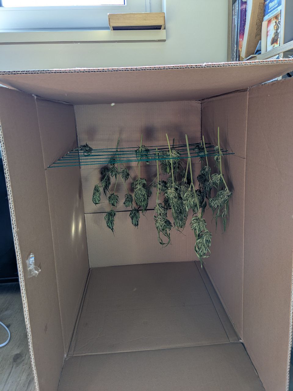
Last night a friend of mine dropped off his most recent harvest, a modest amount of wet weed.
We both started this year with one month difference, and I wanted to build a "smart dry-box" anyways, so I told him to pass it on to me for some time.
This allows me to gather some data points and build a solution until my plant is done.
Somehow I expect a bigger yield than him.
Now here's the thing, the current boss fight! :)
The idea
I have several RaspberryPi's and an Arduino Uno with several sensors laying around, that I want to use to build something useful.
Hence, I figured I will build a "smart" ventilation system, with sensors and some other things!
Here's the plan
- We need to gather environment data about
- Humidity
- Temperature
- add ventilator
- Analyze data after adding the ventilator
- Improve ventilation if needed
- Reiterate from 3.
I will use in the beginning an Arduino Uno and not collect any data points, rather just act on current values. Later, I want to connect a RaspberryPi and read from the Arduino's buffer, to store the data.
Unfortunately, over night my whole flat started to smell very strong, hence in the best case we're even able to do something against that!
I've currently added an air filter into the box, but due to lack of ventilation it doesn't really do anything.
Day 1
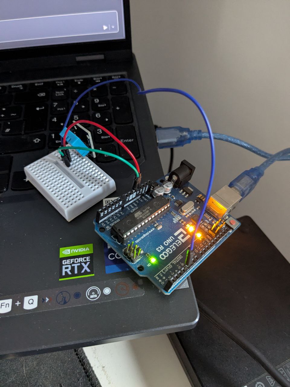
Today I've set up the Arduino Uno on my laptop.
For that I installed
- arduino-cli
- screen
- neovim extension: https://github.com/stevearc/vim-arduino
After installing arduino-cli we need to ensure that our current user $UID is part of the uucp group
> sudo usermod -aG uucp phil
And from the hardware side I gathered
- 1x Arduino UNO with USB-cable
- 1x DHT11 sensor (Temperature and Humidity)
- 1x small breadboard to connect components
- 3x wires
On the initial setup of the Arduino I needed to install required firmware/drivers
> arduino-cli core install arduino:avr
once that finished we can start working on our project.
First I created an empty directory weedar and initialized git in it.
Ready for take-off!
First things first, the "Hello World".
For that we create a file weedar.ino with the contents
void setup() {
  // put your setup code here, to run once:
  Serial.begin(9600); // refresh rate in ms
}

void loop() {
  // put your main code here, to run repeatedly:
  Serial.println("Hello World!"); // push string to buffer
  delay(1000); // wait for some time (1000 ms)
}
after adding the file we can compile it using
> arduino-cli compile --fqbn arduino:avr:uno weedar.ino
Great! We have our hello world compiled, now we just need to push it onto the Arduino.
For that we first connect the Arduino. Usually it's detected and connected right away, you can verify that with
> arduino-cli board list
Port         Protocol Type              Board Name  FQBN            Core
/dev/ttyACM0 serial   Serial Port (USB) Arduino Uno arduino:avr:uno arduino:avr
You should see your device there.
We push our code using
> arduino-cli upload -p /dev/ttyACM0 --fqbn arduino:avr:uno weedar.ino
Don't worry, later we might even build a make file to get rid of all of this manual work =D
To read from the Arduino we simply can do a
> cat /dev/ttyACM0
which opens up a stream and will for ever read.
Hello World!

Hello World!
...
Be warned, interrupts cause data loss.
Next, I wanted to read temperature and humidity from the DHT11. Which was surprisingly easy.
I looked up the manual for the Olegoo Arduino UNO Starter Kit, followed the wiring diagram and copied the code to read from the sensor and write to the buffer.
Here's the wiring diagram
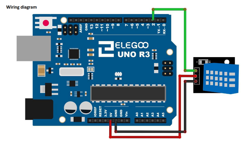
We'll add a breadboard in between, tho.
I don't want to force you guys to download the Olegoo starter kit, so we'll be using a different implementation that I found here
#include <dht11.h>
#define DHT11PIN 4

dht11 DHT11;

void  setup()
{
  Serial.begin(9600);
}
void loop()
{
  Serial.println();

  int chk = DHT11.read(DHT11PIN);

  Serial.print("Humidity (%): ");
  Serial.println((float)DHT11.humidity, 2);

  Serial.print("Temperature  (C): ");
  Serial.println((float)DHT11.temperature, 2);

  delay(2000);
}
Before we can compile that, we need to install the library that gives us dht11.h with the command
> arduino-cli lib install --git-url 'https://github.com/adidax/dht11'
This will initially most likely fail, because we didn't configure the arduino-cli fully, yet.
To allow the installation of external libraries via git we need to update the configuration
> arduino-cli config set library.enable_unsafe_install true
Then hit again
> arduino-cli lib install --git-url 'https://github.com/adidax/dht11'
Then
- compile
- sync
and finally reading the buffer
> cat /dev/ttyACM0
Humidity (%): 23.0
Temperature (C): 22.3

Humidity (%): 23.0
Temperature (C): 22.3
...
That covers all for today.
Tomorrow, I will update the commands and add some pictures as well as connect the ventilator and a small debugging display.
Day 2
I've started the day with fixing the content of yesterday, provided images and commands.
Afterwards, I started with the next big step: Ventilation.
For ventilation I originally wanted to use an old PC fan that I have laying around. But because it requires 12V, and the Arduino only delivers 3.3V or 5V, I will use a simple 5V DC motor for the first version.
To combine yesterdays implementation with the ventilator I will use these things today:
- Arduino UNO with USB-cable
- DHT11
- Arduino Prototype Board (incl. small breadboard)
- a bunch of wires
- 5V DC motor with rotor blade
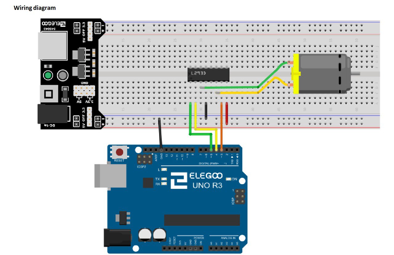
- L293D controller
The first iteration started exactly like yesterday.
I followed the wiring diagram, and copy-pasted the code from the Starter Kit
And the script
//www.elegoo.com
//2016.12.12

/************************
Exercise the motor using
the L293D chip
************************/

#define ENABLE 5
#define DIRA 3
#define DIRB 4

int i;

void setup() {
  //---set pin direction
  pinMode(ENABLE,OUTPUT);
  pinMode(DIRA,OUTPUT);
  pinMode(DIRB,OUTPUT);
  Serial.begin(9600);
}

void loop() {
  //---back and forth example
    Serial.println("One way, then reverse");
    digitalWrite(ENABLE,HIGH); // enable on
    for (i=0;i<5;i++) {
    digitalWrite(DIRA,HIGH); //one way
    digitalWrite(DIRB,LOW);
    delay(500);
    digitalWrite(DIRA,LOW);  //reverse
    digitalWrite(DIRB,HIGH);
    delay(500);
  }
  digitalWrite(ENABLE,LOW); // disable
  delay(2000);

  Serial.println("fast Slow example");
  //---fast/slow stop example
  digitalWrite(ENABLE,HIGH); //enable on
  digitalWrite(DIRA,HIGH); //one way
  digitalWrite(DIRB,LOW);
  delay(3000);
  digitalWrite(ENABLE,LOW); //slow stop
  delay(1000);
  digitalWrite(ENABLE,HIGH); //enable on
  digitalWrite(DIRA,LOW); //one way
  digitalWrite(DIRB,HIGH);
  delay(3000);
  digitalWrite(DIRA,LOW); //fast stop
  delay(2000);

  Serial.println("PWM full then slow");
  //---PWM example, full speed then slow
  analogWrite(ENABLE,255); //enable on
  digitalWrite(DIRA,HIGH); //one way
  digitalWrite(DIRB,LOW);
  delay(2000);
  analogWrite(ENABLE,180); //half speed
  delay(2000);
  analogWrite(ENABLE,128); //half speed
  delay(2000);
  analogWrite(ENABLE,50); //half speed
  delay(2000);
  analogWrite(ENABLE,128); //half speed
  delay(2000);
  analogWrite(ENABLE,180); //half speed
  delay(2000);
  analogWrite(ENABLE,255); //half speed
  delay(2000);
  digitalWrite(ENABLE,LOW); //all done
  delay(10000);
}
Now as you can see we can move the rotor into two different directions,
one will move air away from the motor (DIRB), the other one towards the motor (DIRA).
Apart from that we can turn the motor on analogWrite(ENABLE,HIGH) or off analogWrite(ENABLE,LOW).
By passing a value between 0 and 255 to ENABLE we can adjust the rotation speed.
Again, I compiled the code and uploaded it to the Arduino to check if everything was working as expected.
That being said I integrated the motor code into the previous code base for the DHT11 sensor
#include <dht11.h>
#define DHT11PIN 5

#define DC_ENABLE 4
#define DC_DIRA 3
#define DC_DIRB 2

int i;


dht11 DHT11;

void  setup()
{
  //---set pin direction
  pinMode(DC_ENABLE,OUTPUT);
  pinMode(DC_DIRA,OUTPUT);
  pinMode(DC_DIRB,OUTPUT);
  Serial.begin(9600);
}
void loop()
{
  int chk = DHT11.read(DHT11PIN);

  Serial.print("Humidity (%): ");
  Serial.println((float)DHT11.humidity, 2);

  Serial.print("Temperature  (C): ");
  Serial.println((float)DHT11.temperature, 2);

  if((float)DHT11.temperature >= 35.0){
    Serial.println("FAN START");
    digitalWrite(DC_ENABLE,HIGH);
    digitalWrite(DC_DIRB,HIGH);
  } else if ((float)DHT11.temperature >= 30.0) {
    Serial.println("FAN START");
    digitalWrite(DC_ENABLE,127);
    digitalWrite(DC_DIRB,HIGH);
  } else if ((float)DHT11.temperature > 25.0) {
    Serial.println("FAN START");
    digitalWrite(DC_ENABLE,127);
    digitalWrite(DC_DIRB,HIGH);
  } else {
    Serial.println("FAN STOP");
    digitalWrite(DC_ENABLE,LOW);
    digitalWrite(DC_DIRB,LOW);
  }
  delay(2000);
}
Cool, with this our motor will turn on for any temperature bigger than 25 degree Celsius with different steps and will be off otherwise.
Time to get the wiring done.
This time, instead of following a diagram I needed to come up with my own solution.
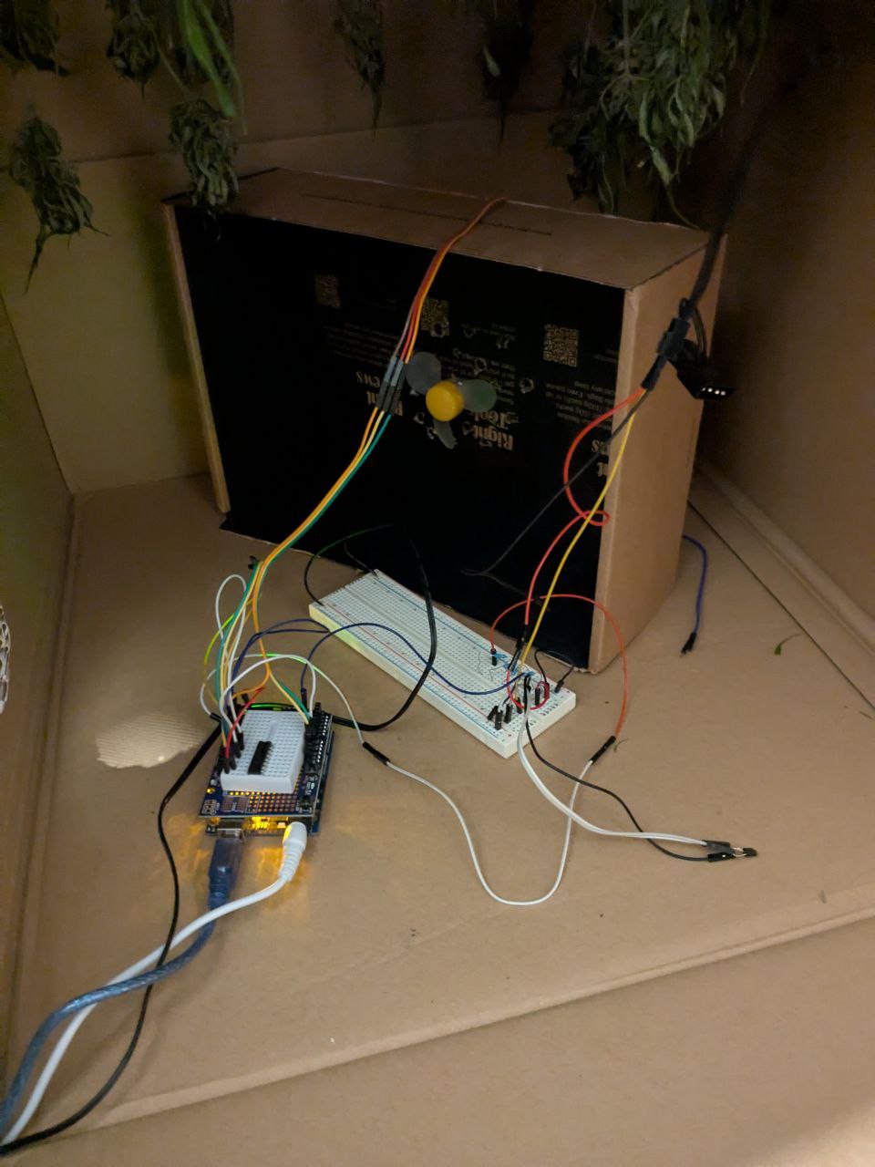
Here's an image of it
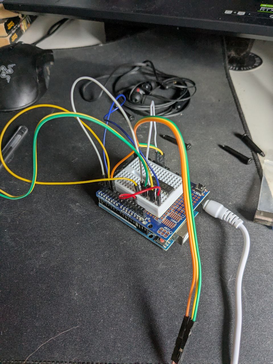
You can see that I'm using the Prototype Board now and I've translated the DHT11 combined with the 5V DC motor wiring onto it.
Because we're using the Arduino directly we can omit some of the wires, which is cool.
Apart from that I've moved the AC plug from the breadboard + AC module to the Arduino.
Now it can run without my laptop and I can patch the soft- and hardware however I want - although I will for sure turn it off whenever I patch hardware =D
I stuffed the motor into a smaller card box that I had laying around. So without any further ado...
Let me introduce to you "Prototype #1"!
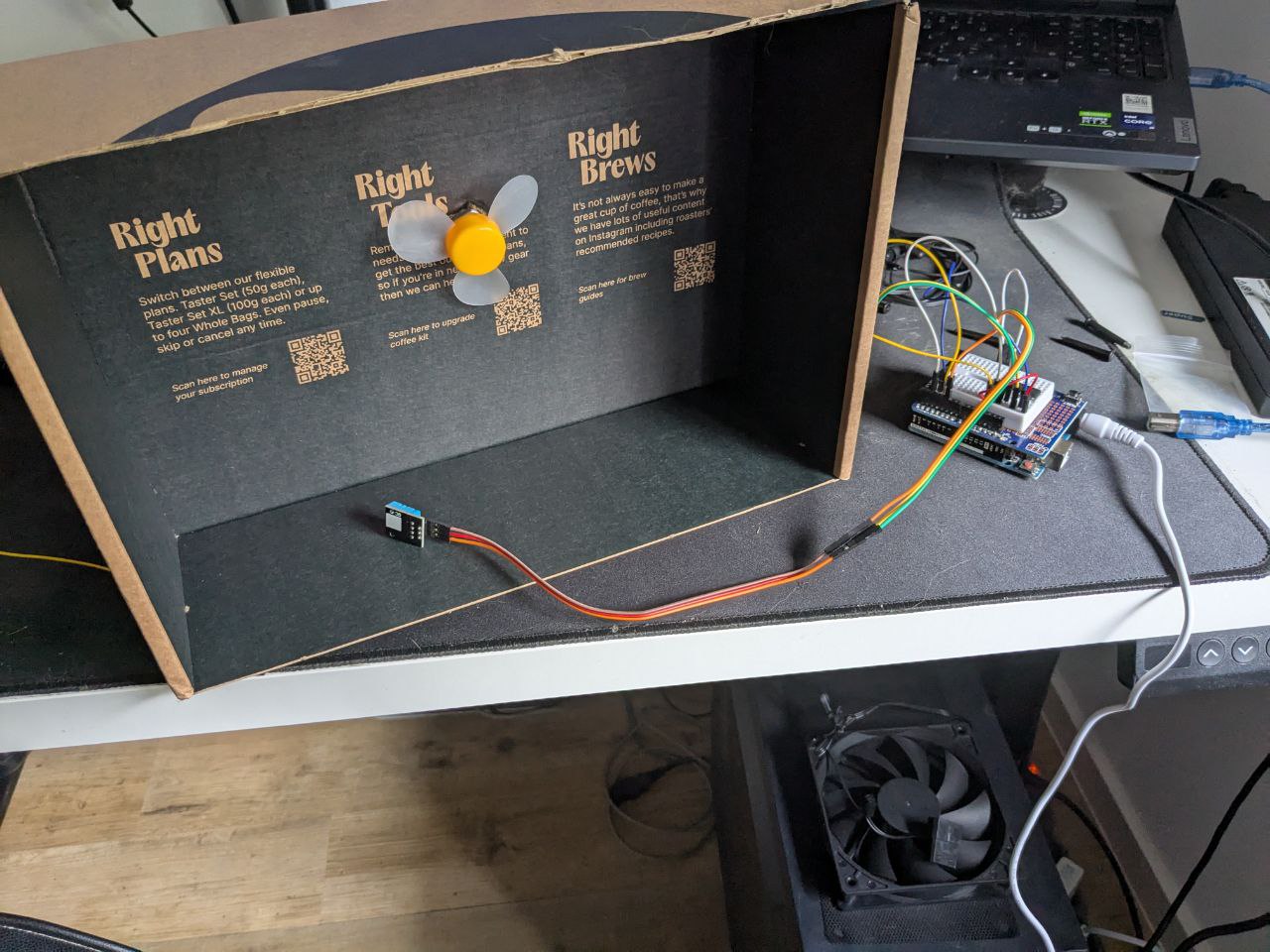
And in action
The DHT11 sits on top of the vent box, and the ventilator points into the direction of a secured new hole that sits on the bottom of the dry box.

Whew, that was relatively quick to solve!
Now let's hop onto the next challenge.
I wanna analyze the data to improve my solution upon it!
To do that, I hooked the Arduino via USB to one of my RaspberryPi's.
This one is running pi-hole in my network. It's kinda already running and collecting data, so why not!
Well... I didn't touch this Pi for a very long time - apart from keeping pi-hole up to date.
Hence, a beloved old and very outdated environment greeted me
pi@raspberrypi:~/weedar $ python --version
Python 2.7.16
pi@raspberrypi:~/weedar $ python3 --version
Python 3.7.3
Yikes!
But better than nothing, and because I am unsure if pi-hole needs any of that we'll just keep rolling!
To speed up the process - and because I don't like building full stack apps, I asked ChatGPT for help with a quick monitoring setup.
You can find the conversation here.
I followed it's instructions, which were fairly simple and obvious after seeing the setup.
Sweet, now we have a monitoring tool and a first attempt to improve the box!
Time to talk about our goal.
When drying cannabis, the goal is to preserve cannabinoids, terpenes, and aroma while preventing mold. The commonly recommended conditions are:
Temperature: 60–70 °F (15–21 °C)
- Too warm (>75 °F / 24 °C) can degrade terpenes and dry the buds too quickly.
- Too cold (<55 °F / 13 °C) slows drying excessively, raising mold risk.
Relative Humidity (RH): 50–60%
- Lower than 45% RH can make the buds dry too fast, leaving them harsh.
- Higher than 65% RH risks mold and uneven drying.
🌱 Ideal target:
- 65 °F (18 °C)
- 55% RH
We're at a constant level of 25 degree Celsius and 37% RH.
Time to think about a soltion! Yey!!!
But that's for tomorrow.
To wrap things up I installed screen on my RaspberryPi,
terminated all running scripts and then ran
> screen

> python collector.py & python server.py &
And detached from the screen session via CTRL + a followed by d.
See ya tomorrow!
Day 3
Before I begin with the intro for today a quick note from yesterday.
After finishing the post update I went ahead and had one more iteration with ChatGPT on the interface, updated the local version and ran it on the Pi.
Apart from that I also added a second hole to the top if the box. You will see a picture later on. But keep that in mind for a second. The fan still blows air out in the bottom of the box.
So today starts with a quick physics lesson.
Warm air can hold a little amount of water.
Cold air can hold more water.
Warm air is light and therefore floats ontop of cold air. So to get rid of warm air you need to pull it out on top.
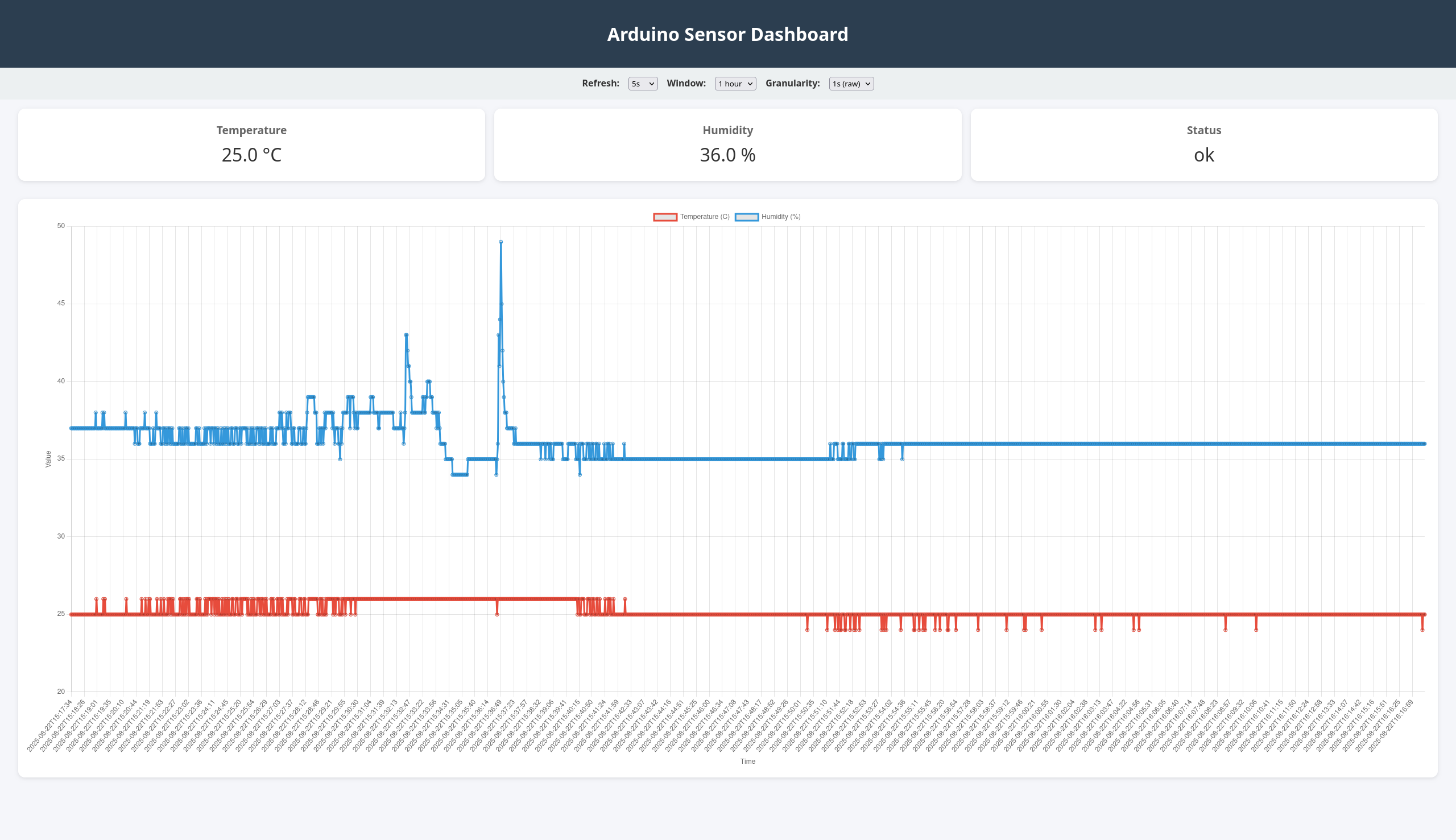
Here's a screenshot of the dashboard right now

In our case with 23 °C and 38% RH we need more cold air and get rid of the warm one.
Hence, one of todays todos is to put the ventilator on the top hole.
As earlier stated, the Arduino provides 5V, but the fan requires 12V.
Time for tinkering!
But before I need to research if and how this is possible. I technically can use a 12V wall plug and wire it.
But I need the wiring for the plug as well as the ventilator.
After a quick safety research before
I was sure that anything with 12V wouldn't be terrible and hurt me too much.
Nothing happened so far!
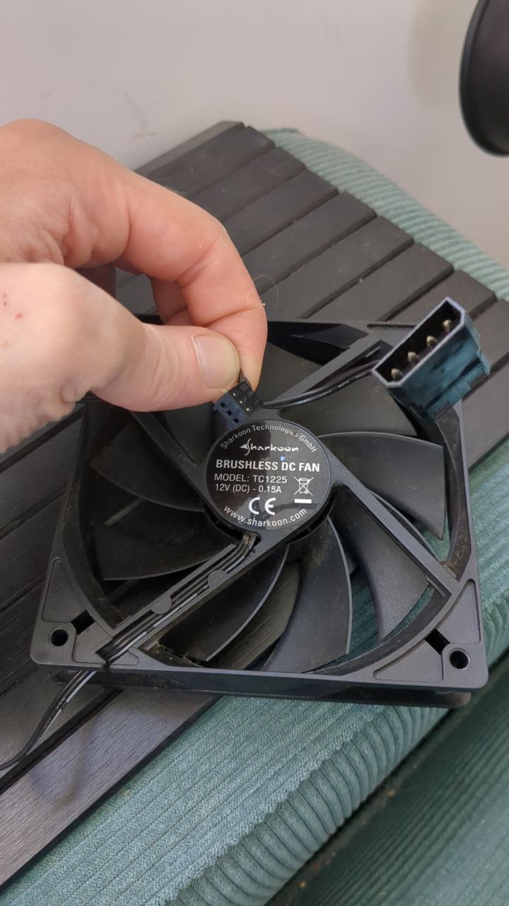
So the internet says that for the fan the wiring is, looking onto the outgoing wires
- left: ground
- middle: +12V
- right: Tach (read only)
The wall plug on the other hand is gonna be more of a trial and error.
I smashed a quick circuit together, connected a contact of the plug to the left and the other to the middle contact... Nothing. Obviously, once I changed the connections everything started working.
Notice the drink right next to it - keeping up the safety! Here's a picture, for a closer lookup
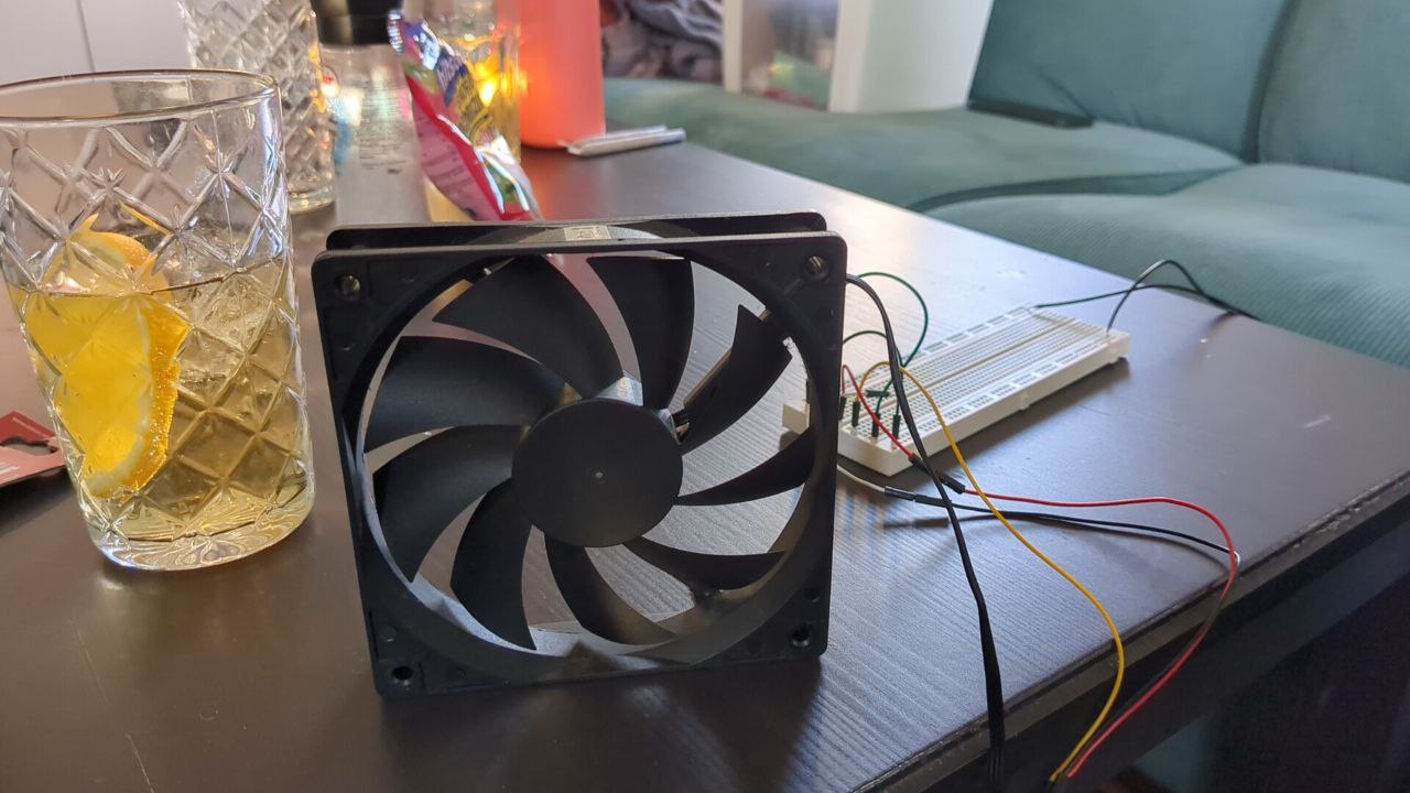
Oh, and do you see the black cable going into the breadboard? Right, that's the 12V plug :))))
Please do not build this at home! I am highly unprofessional.
I quickly smashed things together and with the help of the internet build a wiring that connects the Arduino with the fan and allows it to control the speed of the rotor.
Using a 2N2222A-1726 npn transistor and in total 250Ω of resistors (1x 220Ω and 3x 10Ω chained in row).
It's pretty simple. And once you figured out which contact is which of the transistor it actually makes sense. We add the resistors to protect the Arduino from the 12V we use for the fan, apart from that everything is the same circuit - apart from the transistor that acts like a gate.
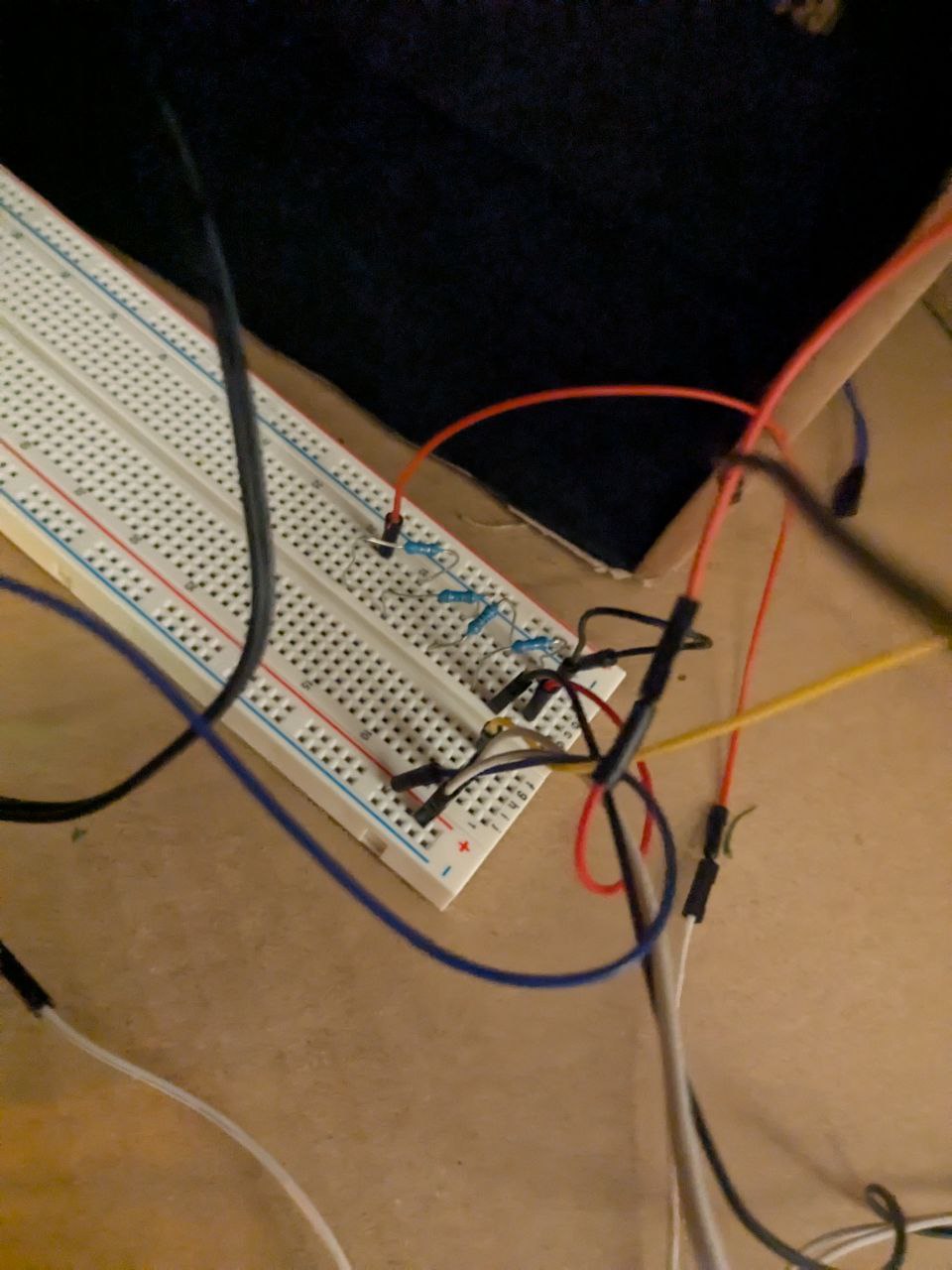
Interestingly, if you fuck up the outer pins of the transistor you create a closed circuit and the fan starts. If you don't understand that this is bad - you will either feel, smell or see your failure because you're currently frying your transistor :) DON'T DO IT
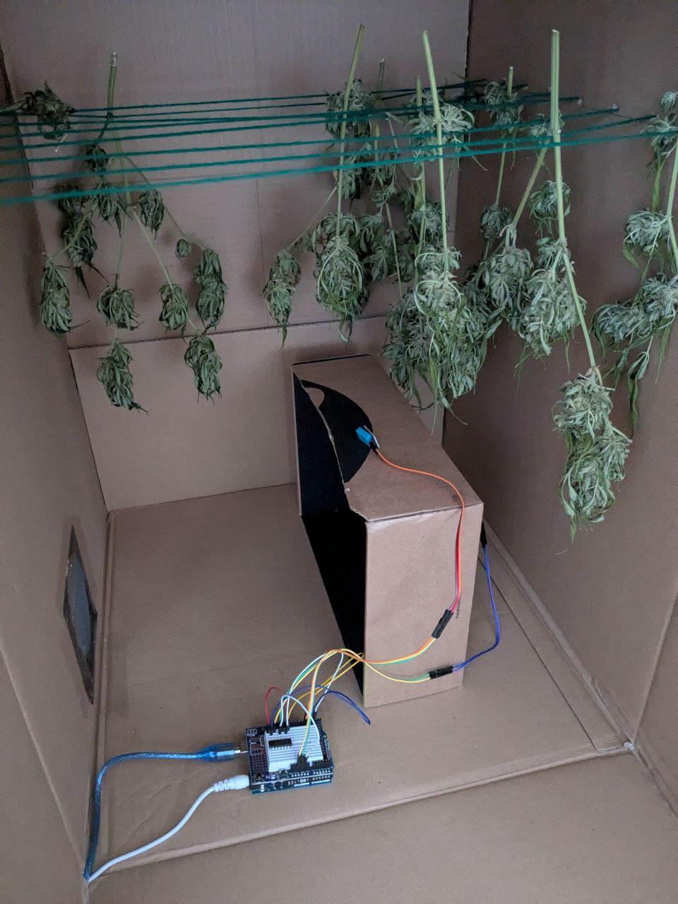
Once this was done I smashed all together and put it into the box.
I fixed the fan on top of the box, blowing air out. From the outside I fixed it with BIC roller pens, the inside is holding the fan and the caps are holding the insides. It works surprisingly well!
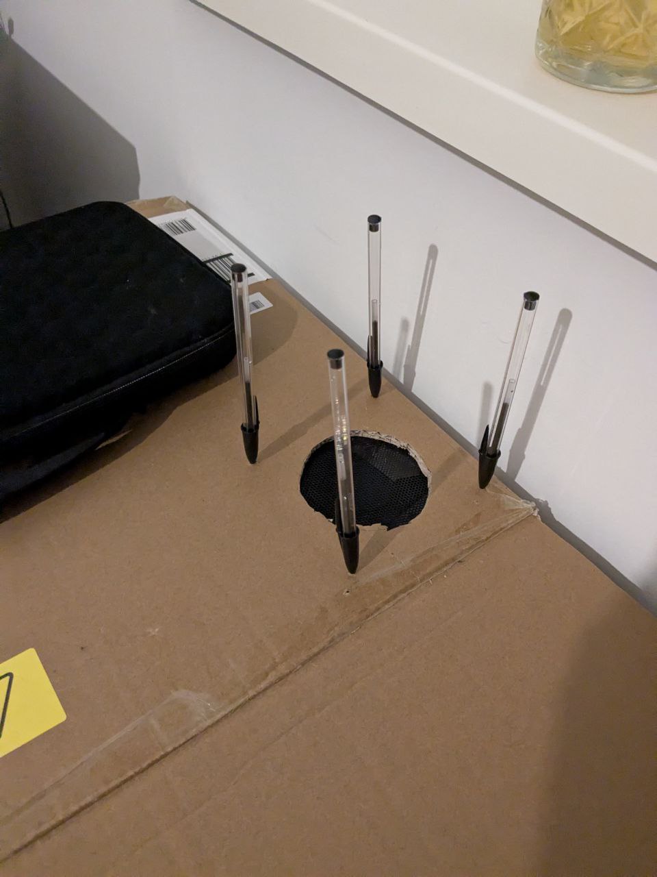
Together the insides now look like this:
Alright, more monitoring with the new solution until tomorrow!
Day 4
Today I don't have much time to actively contribute to the build. But I asked ChatGPT to refine the dashboard a little bit
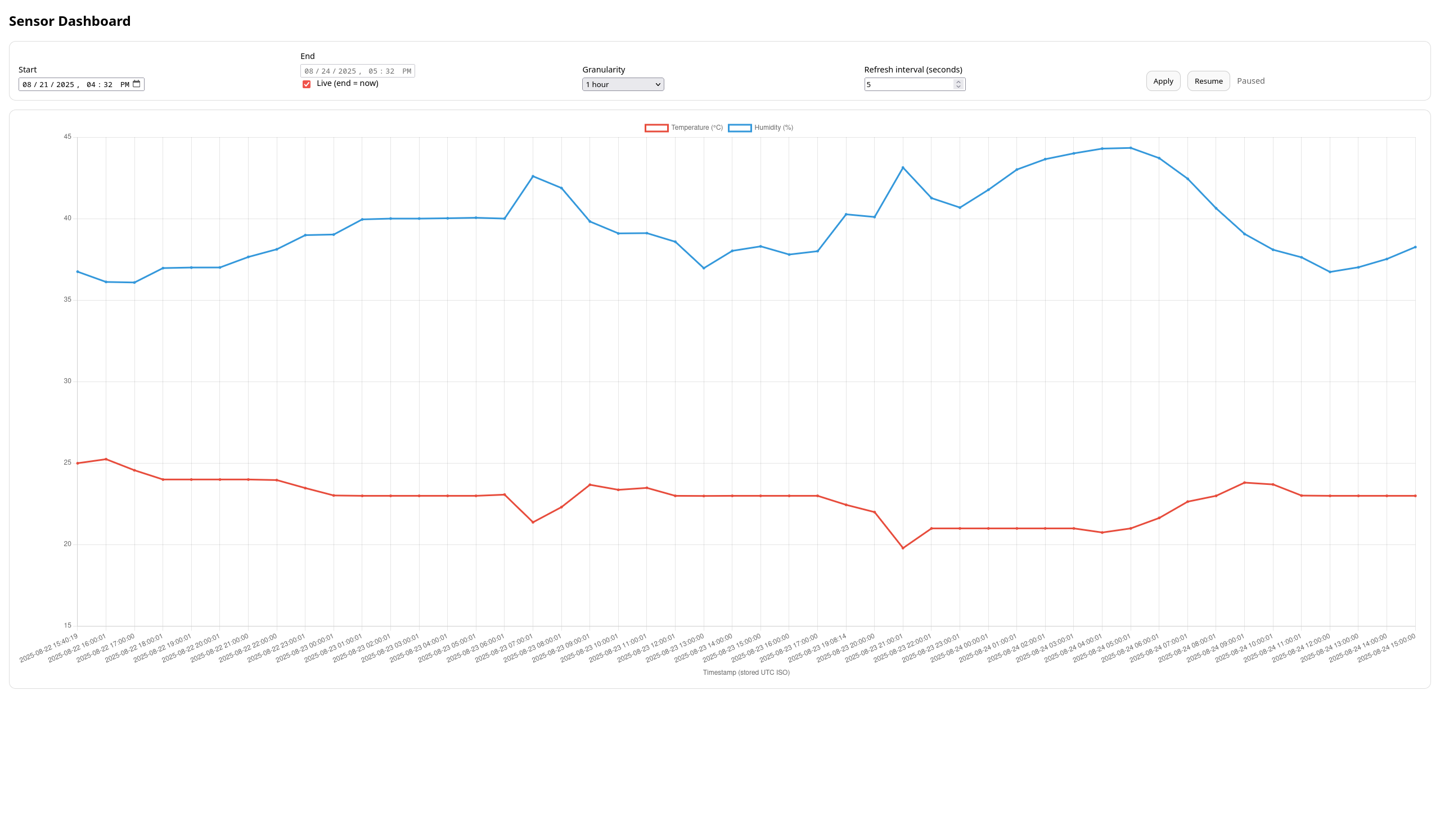
We can now query for bigger time windows and set the step size of the graph.
Now who would have thought we will see something like the cosine curve here right away =D
For me as a mathematician this is lovely!!
Basically since last night, when I changed the fan, we started to have a controllable environment!
I experimented with different approaches how to run the fan to bring up the humidity inside the box.
Additionally, I added a cup of water into the box which acts as a very small source of humidity.
Unfortunately, nothing worked and throughout my experiments I broke the 12V fan.
Luckily, it was Sunday morning when I noticed and not Saturday, so I immediately ordered a replacement on Amazon.
I opted for a pack of 3x little 3.3-5V fans that usually cool Raspberry Pi CPUs.
Because I was too afraid of an uncontrolled environment I ordered them together with other things like more DTH11s with early morning delivery.
In the box I reverted everything to the state of day 1 and called it a day.
Day 5
Amazon fucked up =)
I didn't receive the fans in my order.
So I placed yet another order, but this time 3 extremely powerful 12V fans. I would assume the reader to think now about the reason. And that reason is quite simple.
First, it poured rain since a few days, and whenever I open a window the room that holds the box gets flooded with humid air. Second, there is not really an air exchange happening between the box and the room. Inside the box is a more or less constant temperature of 25 degree Celsius which causes the water inside the cup to evaporate. And because of that we're today on 60% humidity, rising. If we don't manage to get this fixed before we reach a constant level of >65% we risk the buds to get mouldy and we don't want that for our friend!
It's better to fuck up the tricomes or mess up all of the drying than get it wet and mouldy!
Day 6
Captain, we've reached dangerous territory!
Humidity is at 65% with little tendencies to raise.
The fans arrived and I immediately deployed one on top of the box to pull out warm air.
I continue monitoring until tomorrow.
Day 7
Today is the final project day. I didn't plan to spend more than 7 days on this, anything past that point wouldn't justify spending the time on it anymore, because then I could manually adjust environment parameter, i.e. humidity and temperature.
I am very confident in the claim that one of the biggst hurdles of this project was the cardboard box environment.
Cardboard just has this amazing property of sucking in humidity like a sponge and then not releasing it anymore. And I felt this whenever I spend a little more time than usual next to it, or worked next to it after a humid day - like days 2-3.
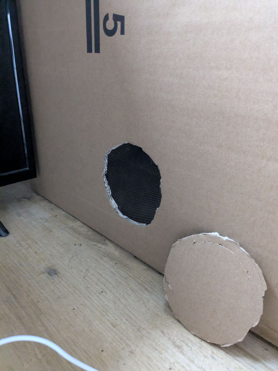
Another problem was created by the position of the ventilation holes of the box - which I could fix quickly.
First, the holes allowed debree and dust to get into the system, which we don't want in this particular case.
But also the positioning enabled the airstream to not affect the whole volume of the box. This caused temperature and air to get stuck on the back of the box, whilst the front was in constant movement.
Obviously, this affected the drying process for the full batch.
Finishing this article, whenever I got time... :(
I know I still owe you several bits of information, a full conclusion and a full part list ;)